ACI AFS-460-137 : Differential Pressure Switches (Metal), 0.60 to 12.0" wc , DPDT Contact, Manual Reset, Compression Fitting, 2 Year Limited Warranty
Application
Model AFS-460–137 is a general purpose proving switch with DPDT contacts for 24V ac applications, and a manual reset feature that requires operator intervention whenever it actuates. It can be used to sense positive, negative, or differential air pressure in HVAC and Energy Management applications.
Description & Operation
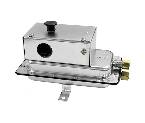
The plated housing contains a diaphragm, a calibration spring, a snap-acting SPST-NC switch with manual reset button, and a DPDT relay installed on the snap switch at the factory. The DPDT feature consists of a relay- pack circuit board assembly containing a power connection terminal block and a DPDT slave relay with two form-C 8-Amp contacts connected to two terminal blocks.
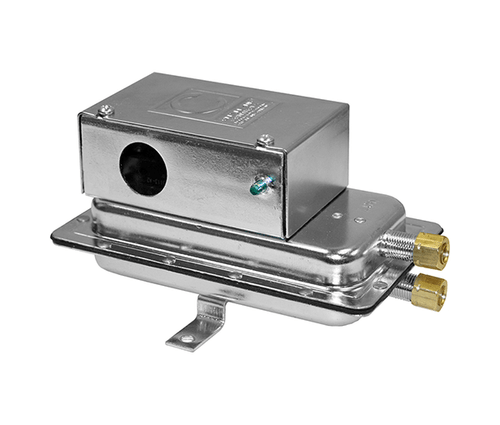
The sample line connections located on each side of the diaphragm accept .25" OD tubing via the integral compression ferrule and nut.
An enclosure cover guards against accidental contact with the live switch terminal screws and the set point adjusting screw. The enclosure cover accepts two 0.5" conduit connections. The manual reset button is located on the top surface of the enclosure cover.
The Model AFS-460–137 is designed to accept firm-wall sample lines of 1⁄4" OD tubing by means of ferrule and nut compression con- nections. Optional adapters (P/N 28698-001) are available for slipping on 3⁄16" ID or 1⁄4" ID flexible tubing. For sample lines of up to 10 feet, 1⁄4" OD tubing is acceptable. For lines up to 20 feet, use 1⁄4" ID tubing.
Select one of the following five application options and connect the sample lines as recommended.
- POSITIVE PRESSURE ONLY: Connect the sample line to inlet H; inlet L remains open to the atmosphere.
- NEGATIVE PRESSURE ONLY: Connect the sample line to inlet L; inlet H remains open to the atmosphere.
- TWO NEGATIVE SAMPLES: Connect the higher negative sample to inlet L. Connect the lower negative sample to inlet H.
- TWO POSITIVE SAMPLES: Connect the higher positive sample to inlet H. Connect the lower positive sample to inlet L.
- ONE POSITIVE AND ONE NEGATIVE: Connect the positive sample to inlet H. Connect the negative sample to inlet L.
Before pressure is applied to the diaphragm, the snap switch contacts will be in the normally closed (NC) position. As differential pressure rises above the field adjustable set point, the snap switch opens, de-energizing the coil on the slave relay, which activates the DPDT contacts. An LED indicates that the snap switch exceeds differential set point. It remains lit until the manual reset push button is depressed.
Field Adjustment
The AFS-460–136 Manual Reset Air Switch has an adjustment range of 0.40 to 12.0" wc, ±.06" wc. To adjust the set point: Turn the adjusting screw counterclockwise until motion has stopped. Next, turn the ad- justing screw 4 complete turns in a clockwise direction to engage the spring. From this point, the next ten turns will be used for the actual calibration. Each full turn represents approximately 1.16" wc.
Please note: To properly calibrate an air switch, a digital manometer and air pressure source should be used to confirm the actual set point.
Specifications
| Input Pressure Range | AFS-460: 0.40 +/- 0.06" to 12.0" wc |
| Set Point Range | AFS-460: 0.40 +/- 0.06” to 12“ wc |
| Field Adjustable “Operate” Range | AFS-460: 0.46" to 12" wc |
| Field Adjustable “Release” Range | AFS-460: 0.46"w.c. to 11.2" w.c. |
| Approximate Switching Differential | Progressive, increasing from 0.02 +/- 0.01" wc @ minimum set point to 0.8" wc @ maximum set point |
| Contact (Load) Rating | AFS-460: 15A @ 125, 250, or 277 VAC / 1/2A @ 125 VDC, 1/4A @ 250 VDC / ¼ hp @ 125 VAC, ½ hp @ 250 VDC AFS-460-137: 8A @ 250 VAC |
| Contact Arrangement | AFS-460: SPST-NC w/ Manual Reset |
| Media Types | AFS-460: Air |
| Maximum Pressure | 0.5 PSI (0.03 Bar) |
| Life Expectancy | AFS-460: 6,000 cycles minimum @ 1/2 psi (0.03 Bar) max pressure / cycle & max load |
| Operating Temperature Range | -40 to 180ºF (-40 to 82ºC) |
| Operating Temperature Range | 10 to 95% RH, non-condensing |
| Mounting Direction | Any vertical plane |
| Enclosure Material | Galvanized Steel |
| Sample Line Connections | Accepts ¼” OD rigid or semi-rigid metallic tubing using integral compression fitting, ferrule and nut “-112 Option”: Includes two barbed fittings that accepts ¼” flexible plastic tubing |
| Electrical Connections | Screw type terminal with cup washers |
| Conduit Knockouts | Accepts ½” Conduit (7/8” (22.3 mm) opening) |
| Dimensions (H x W x D) | 6.25” x 4.46” x 3.18” (158.8 mm x 113.3 mm x 80.8 mm) |
| Product Weight | 1.2 lbs (0.544 kg) |
| Agency Approvals | UL, CUL, FM, CSA, CE, ISO 9001: 2008 |
Datasheets
- Pressure Range:
- 0.60 to 12.0
- Reset:
- Manual


