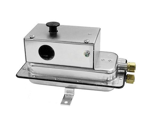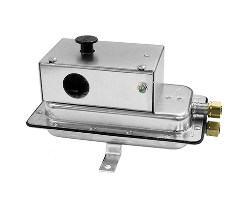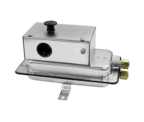


The ACI AFS-460-DSS is a dual differential pressure switch designed for HVAC and Energy Management applications that need lead/lag staging from a single sensing device. The galvanized-steel plated housing contains a diaphragm, calibration spring, and two snap-acting SPST-NC switches sharing a single manual reset button. Use it for 120 VAC applications that need two manual-reset switching points off one airflow proving measurement: Switch A (lead) trips first at the lower set point, and Switch B (lag) trips at a higher pressure as a percentage above Switch A (5% to 35% above, depending on the configured set-point band). Set point range is 1.25-12 inWC, with the lag offset varying from 5% at the low end to 35% at the high end. The enclosure cover guards against accidental contact with the live switch terminal screws and accepts two 0.5" (12.7 mm) conduit connections; the manual reset button is on the top surface. Made in USA by ACI in Middleton, Wisconsin.
This switch is best suited for lead/lag staging applications where a single differential pressure measurement needs to trigger two distinct actions at different thresholds - typical uses include staged fan or pump alarm cascades, primary/backup equipment switching, filter-load alarm at one threshold and replacement-required alarm at a higher threshold, and dual-zone HVAC control logic from a single sense point. Manual reset on both switches ensures operator intervention is required before either point re-arms. Per ACI's published applications: monitoring filter blockage, proof of flow, prove excessive or insufficient flow, alarms and control.
Key Features
Two independent snap-acting SPST-NC switches share a single sensing diaphragm, providing staged switching from one differential pressure measurement. Switch A (lead) is set to the primary threshold; Switch B (lag) trips at a higher pressure as a percentage above A: 5% offset for the 1.25-3.0 inWC band, 10% for 3-6 inWC, 15% for 6-9 inWC, and 35% for the 9-12 inWC band. Both switches latch in their tripped state and require manual reset via the single button on the enclosure top.
Set point is field-adjustable across the entire 1.25-12 inWC range via the on-board adjustment screw. Calibration procedure: turn the adjustment screw counterclockwise until motion stops, then turn 4 complete turns clockwise to engage the spring; the next 10 turns are the calibration range. Each full turn represents approximately Field-adjustable via set point screw. ACI recommends using a digital manometer or other measuring device to confirm the actual set point during calibration.
Integral compression fittings with ferrule and nut accept 1/4" OD rigid or semi-rigid metallic tubing - the professional choice for permanent installations where vibration resistance and long-term seal integrity matter. For sample lines up to 10 feet, 1/4" OD tubing is sufficient; for runs up to 20 feet, use 1/4" ID tubing; for runs 20-60 feet, step up to 1/2" ID tubing to maintain response time. If flexible tubing is preferred, an optional 1/4" OD slip-on adapter (P/N 18311) is available, or order the -112 variant with barbed fittings included.
The diaphragm must be mounted in any vertical plane to achieve the lowest specified operating set point - mounting with the diaphragm horizontal will introduce gravity bias and prevent the switch from reaching its lowest rated trip point. Surface-mount via two 3/16" diameter holes in the integral mounting bracket (mounting holes are 3-7/8" apart). Avoid mounting with the sample-line connections pointing upward to prevent condensate from accumulating in the tubing.
Screw-top terminals with cup washers (8-32 screws on AFS-460) accept standard 14-22 AWG wire. The enclosure cover has a 7/8" opening that accepts 1/2" conduit connections (the AFS-460-DSS cover accepts two such connections for separate switch wiring). An enclosure cover guards against accidental contact with the live terminal screws and the set-point adjusting screw.
Plated galvanized steel housing provides corrosion resistance and mechanical durability for HVAC equipment-room and rooftop-unit installations. The internal diaphragm material is compatible with air or combustion by-products that will not degrade silicone. Maximum pressure tolerance: 0.5 psi (0.03 bar, 3.45 kPa) - well above the operating set-point range, providing headroom for transient pressure spikes from damper slams or fan start-up surges.
Tested to Exceeds UL-recognized mechanical endurance test of 6,000 cycles minimum at 0.5 psi (3.45 kPa) maximum pressure each cycle and at maximum electrical load. The 100,000-cycle rating on auto-reset SPDT variants reflects the lighter mechanical stress from snap-back operation, while the 6,000-cycle rating on manual-reset variants reflects the heavier mechanical action of the reset mechanism plus higher inductive ratings on the contacts.
Technical Specifications
| Specification | Detail |
|---|---|
| Product Type | Differential air pressure switch, snap-acting |
| Input Pressure Range | 1.25-12 inWC (+/-0.06 inWC tolerance on AFS-460 series, +/-0.02 inWC on AFS-222/262) |
| Set Point Range | 1.25-12 inWC |
| Field-Adjustable Operate Range | 1.31 to 12.0 inWC |
| Field-Adjustable Release Range | 1.31 to 11.2 inWC (approximate) |
| Switching Differential | Lag switch B: up to 5% (1.25-3.00 inWC range), 10% (3-6 inWC), 15% (6-9 inWC), or 35% (9-12 inWC) after switch A |
| Contact Arrangement | 2 SPST-NC Lead/Lag (manual reset) |
| Contact (Load) Rating | 15A at 125, 250, or 277 VAC; 1/2A at 125 VDC; 1/4A at 250 VDC; 1/4 hp at 125 VAC; 1/2 hp at 250 VAC; 0.5 VA at 24 VAC 50/60 Hz |
| Reset Style | Manual |
| Measured Media | Air or combustion by-products that will not degrade silicone |
| Maximum Pressure | 0.5 psi (0.03 bar, 3.45 kPa) |
| Life Expectancy | Exceeds UL-recognized mechanical endurance test of 6,000 cycles minimum at 0.5 psi (3.45 kPa) maximum pressure each cycle and at maximum electrical load |
| Operating Temperature | -40 to 180 deg F (-40 to 82 deg C) |
| Operating Humidity | 10-95% RH non-condensing |
| Mounting Direction | Diaphragm in any vertical plane (required for lowest set point) |
| Enclosure Material | Galvanized steel, plated |
| Sample Line Connections | 1/4 inch OD rigid or semi-rigid metallic tubing (integral compression ferrule and nut) |
| Electrical Connections | Screw-top terminals with cup washers |
| Conduit Opening | 7/8 inch diameter opening accepts 1/2 inch conduit (two openings on AFS-460-DSS cover) |
| Agency Approvals | UL, CSA approved; CE pending |
| Dimensions (H x W x D) | 6.13 x 3.88 x 3.56 in (155.7 x 98.55 x 90.42 mm) |
| Weight | 1.2 lb (0.544 kg) |
| Mounting Hole Spacing | 3-7/8 in (98.55 mm) apart, 3/16 in diameter holes |
| Calibration Adjustment | Field-adjustable via set point screw |
| Manufacturer | ACI (Automation Components, Inc.) - Middleton, WI USA |
| Manufacturer Part Number | AFS-460-DSS |
| Item Number | 101792 |
| Warranty | 2-Year ACI Limited Warranty |
What's In the Box
- AFS switch with plated galvanized-steel housing, factory-set to a nominal mid-range set point
- Integral mounting bracket (3/16" holes, 3-7/8" apart)
- Installation & Operation Instructions
- Integral compression fittings (ferrule and nut, factory-installed)
- Manual reset button (single button on enclosure top, resets both switches)
- Sample-line tubing - 1/4" OD rigid or semi-rigid metallic tubing for compression fitting
- Slip-on adapter for flexible tubing - ACI P/N 18311 (suitable for slipping on 1/4" flexible plastic tubing if you want to use flexible tubing with the compression-fitting model)
- Sampling pitot tubes for in-duct pressure pickup: PT 3", PT 5.2", PT 7.5", PT 9.7" (foam-gasket, multi-point); SPT-3.5" / SPT-8.0" (aluminum, flat tip, static); VPT / VPT-8" (aluminum, pointed tip, velocity)
- Pickup ports for wall/room pressure taps: A/SP-PUP, A/R-PUP, A/R2-PUP, A/O-PUP-H, A/O-PUP-V
- 1/2" conduit fitting and conduit (if used)
- Wire (14-22 AWG appropriate for the contact load) and disconnect/fuse per local code
Documentation
Frequently Asked Questions
What is the AFS-460-DSS used for?
The AFS-460-DSS is a dual-switch differential pressure proving switch with two SPST-NC contacts (Switch A as lead, Switch B as lag) that trip at different set points from a single sensing diaphragm. It's used in HVAC and Energy Management applications that need staged alarms or control sequences off one airflow measurement - filter-load warning at the lower trip and replacement-required alarm at the higher trip, or staged fan alarm cascades, or dual-zone control logic. Both switches latch in their tripped state and require manual reset.
What is the set point range and how do I adjust it?
The set point range is 1.25-12 inWC, adjustable in the field via the on-board adjustment screw. Procedure: turn the adjustment screw counterclockwise until motion stops, then turn 4 complete turns clockwise to engage the calibration spring; the next 10 turns are the active calibration range. Each full turn represents approximately Field-adjustable via set point screw. Use a digital manometer or other measuring device to confirm the actual set point during calibration - the turn-count is a starting reference, not a precision calibration.
How do I wire the dual switches?
Switch A (lead) and Switch B (lag) each have their own SPST-NC contacts with screw-top terminals and cup washers. Before pressure is applied, both contacts are normally closed (NC). As pressure rises, Switch A trips first at the configured set point, then Switch B trips at the higher offset (5%-35% above Switch A depending on the set-point band). Both switches latch in their tripped state and require manual reset via the single button on top of the enclosure. The cover has two 0.5" (12.7 mm) conduit openings for routing wiring to two separate control circuits if desired.
Why does the switch need to be mounted vertically?
The diaphragm must be in a vertical plane to achieve the lowest specified operating set point. Mounting horizontal puts gravity load on the diaphragm that biases the trip point and prevents the switch from reaching its lowest rated operate range. Also avoid mounting with the sample-line connections pointing upward - condensate will accumulate in the tubing and affect both response time and trip-point accuracy. Surface-mount via the two 3/16" diameter holes in the integral mounting bracket; the holes are 3-7/8" apart center-to-center.
What sample-line tubing should I use?
This switch accepts 1/4" OD rigid or semi-rigid metallic tubing via the integral compression fittings (ferrule and nut). Tubing length guidelines: for sample lines up to 10 feet, 1/4" OD tubing is acceptable; for lines up to 20 feet, use 1/4" ID tubing; for runs from 20-60 feet, step up to 1/2" ID tubing to avoid degrading the response time. ACI offers medical-grade tubing kits in various lengths: A/10' TUBE, A/20' TUBE, A/50' TUBE, A/100' TUBE. Locate the sampling probe a minimum of 1.5 duct diameters downstream from the air source, as close to the center of the airstream as practical.
Which inlet do I connect to - high or low?
Positive pressure only: connect the sample line to inlet H (high); leave inlet L (low) open to atmosphere. Negative pressure only: connect to inlet L; leave inlet H open to atmosphere. Two negative samples: higher negative sample to inlet L, lower negative sample to inlet H. Two positive samples: higher positive sample to inlet H, lower positive sample to inlet L. One positive and one negative sample: positive to inlet H, negative to inlet L. The pressure DIFFERENCE between H and L is what drives the diaphragm.
What accessories do I need for installation?
Required: sample-line tubing (specified above), 14-22 AWG wire appropriate for the contact load, and 1/2" conduit if your install requires conduit routing. Application-dependent: sampling pitot tubes for in-duct pressure pickup (PT 3", PT 5.2", PT 7.5", PT 9.7" foam-gasket; SPT-3.5", SPT-8.0" aluminum static flat tip; VPT, VPT-8" aluminum velocity pointed tip), or pickup ports for wall/room pressure taps (A/SP-PUP stainless, A/R-PUP beige, A/R2-PUP white, A/O-PUP-H / A/O-PUP-V outdoor weatherproof). Keep sample-line runs as short as practical for fastest response time.
What media is this switch compatible with?
Air or combustion by-products that will not degrade silicone. The diaphragm is NOT compatible with: liquids of any kind, refrigerants, corrosive gases (chlorine, ammonia, hydrogen sulfide, acid fumes), or media that will degrade silicone elastomers. Maximum overpressure tolerance is 0.5 psi (3.45 kPa); exceeding this will damage the diaphragm and can cause permanent set-point drift or complete failure. For liquid-pressure switching, see Belimo's wet/wet differential pressure switches in the Liquid Pressure subcategory.
What agency approvals does this switch carry?
This switch is UL, CSA approved; CE pending approved. The UL listing covers the mechanical endurance test of the snap-acting switch mechanism and the electrical isolation between the contact circuit and the diaphragm-sensing portion of the device. For mission-critical safety applications (life-safety smoke control, fire-suppression interlocks), verify the specific agency listings required by your local AHJ - this switch is a general-purpose proving switch, not a UL864 life-safety device.
What's the warranty?
2-Year ACI Limited Warranty - covers manufacturing defects in materials and workmanship under normal use. The full warranty terms are in the front of ACI's Sensors & Transmitters catalog at workaci.com. Manufactured in Middleton, Wisconsin, USA. ZOT Supply is an authorized ACI distributor; warranty claims are processed directly with ACI.
- Series:
- AFS
- Pressure Range:
- 1.25-12 inWC
- Range Class:
- Medium
- Contact Style:
- Dual SPST-NC (Lead/Lag)
- Reset Style:
- Manual
- Sample Line Fitting:
- Compression (1/4 in OD rigid)
- Maximum Pressure:
- 0.5 psi (3.45 kPa)
- Approvals:
- UL, CSA approved; CE pending
- Mounting:
- Any vertical plane
- Made in USA:
- Yes